INTRODUCTION

A diffractive Beam Splitter, or Multispot (MS), is a grating-like periodic diffractive optical element (DOE) used to split a single laser beam into several beams, called diffraction orders, in a predefined configuration.  

The split orders are identical copies of the incident beam, identical in parameters such as size, divergence, intensity distribution, polarization and beam quality.

Grating equation for normal incident illumination:

Where Λ is the Period of the DOE, m is the diffraction order, λ is the wavelength, α is the angle between the diffracted beam of order m and the optical axis.

As any other DOE, a diffractive splitter is manufactured for a specific wavelength. For other wavelengths, the efficiency is reduced, and diffraction angles change. Small deviations on the order of 1-2% from the design wavelength are acceptable.

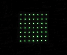
A diffractive Beam Splitter can be designed to generate either a 1-dimensional beam array (1xN) or a 2-dimensional beam matrix (MxN). Design flexibility allows to obtain any configuration of orders and power ratio per order.

The most common usage for MS is increasing laser system throughput by a factor that is equal to the number of split orders. For example, splitting an incident beam to two beams increases the throughput by a factor of two. Our diffractive Beam Splitters are widely used in a variety of medical/aesthetic and industrial applications. Some typical areas include:

  • Medical/aesthetic fractional skin treatments
  • Laser scribing such as in solar cells, displays, and panels
  • Laser welding, soldering
  • Laser dicing/ cutting
  • Laser perforation
  • Dot generation in 3D sensing and machine vision applications
  • IR depth detectors 

Basic optical setups with Diffractive Beam Splitter

There are two typical optical setups with MS elements: a-focal and focal. As it clear from the name in the a-focal case there is no focal plane after the Beam splitter and the image size is linearly scaled with distance from DOE. For the focal case, optimal performance is obtained in the focal plane of the lens placed after the DOE.

For industrial and medical applications, the typically used setup is the focal one, as small spots are required.

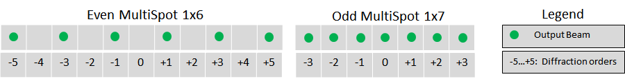
Figure 1: A-Focal setup. Left: image schematically shows splitter to odd (5) number of diffractive orders, and right: image shows splitter to even (4) number of the orders

diffractive beam splitter multispot set up

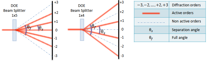
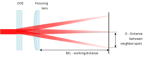
Figure 2: Focal setup with lens (example of Triple Spot shown). Focal spot size is equal to the Diffraction Limited spot size

diffractive beam splitter multispot with focusing lens

Theoretical spot separation calculation by diffractive beam splitter for focal setup:


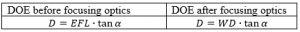
Where EFL – effective focal length, WD – working distance between diffractive surface and focal plane.

Helpful HOLO/OR optical online calculators useful for multispot integration into a system

  1. Beam splitter calculator
  2. Laser beam parameters calculator
  3. Diffraction limited spot size calculator
  4. Binary grating calculator

Typical tolerances table

XY shiftNot sensitive
Z distance from lensNot sensitive
Tip, TiltNot sensitive < +- 10 deg. For higher values an effect is observed in the form of Zero Order
Z rotationDiffraction orders image rotates by the same angle

Zero Order (ZO) for Beamsplitters

ZO is related to manufacturing tolerances that cause a small fraction of incident light to be unaffected by the diffractive pattern. The effect of these tolerances is increased energy on-axis, or in the central spot.
In a MS design with odd diffraction orders number, the ZO is one a of the desired output beams, unlike the case with even orders.

Typically, for very sensitive processes where even a small percentage of the input may affect the process quality, and in applications where efficiency is crucial, we would recommend to use an odd number of spots design rather than an even one.  

For any particular design, the expected ZO values are specified in the data sheet provided to our customers.

 Figure 3 Standard orders configurations for Even and Odd orders values

Zero Order configuration

In our standard MultiSpot products list, the Zero Order energy is displayed as a percentage of the input beam energy for MS with an even number of orders.  In the case of an odd number of  orders, order,it is presented as a percentage of the average energy in the other, desired, orders (assuming 100% transmission efficiency).

Examples:

zero order in even number of spots MS

MultiSpot 1×6 orders with production tolerances. ZO is 1.57% of the input beam

zero order in odd number of spots MS

MultiSpot 1×7 orders with production tolerances. ZO is 74.9% relative to the average of the other desired orders

Please note that for elements with a very large number of spots (approx. > 400 spots), the zero order will be displayed as a percentage of the input beam power and not relative to the other orders.

Design considerations and limitations

Performance comparison between binary and multilevel Diffractive elements

There are two main types of diffractive beam splitters that HOLO/OR offers: binary and multilevel. A binary diffractive pattern has only two levels, and is the “work horse” of diffractive optics. It has advantages of cost effectiveness and manufacturing repeatability, and is suitable for most applications. The drawback of the binary elements is an efficiency of about 80 %. For such cases which require higher efficiency such as high-power industrial laser applications, HOLO/OR offers multilevel elements. These elements have more complex manufacturing processes with higher costs, and can reach efficiencies of >95%.

BinaryMultilevel
Design flexibilityCentro symmetrical dot pattern onlyAny
EfficiencyLimited < ~ 80 %Up to 96 % to certain designs
UniformityVery goodGood
Typical Zero Order0.3-0.6% of input0.05% of input and below
Full angleAvailable at angles up to 40 degrees at 1064nmLimited by manufacturing to ~10 degrees at 1064nm
CostsStandardIncreased

Recommended minimum beam size

HOLO/OR defines the recommended minimum input beam size as 3 times the size of the period of the DOE for an odd number of spots, and 1.5 times the size of the period for an even number of spots. This condition comes from the need to obtain a well-defined separation between neighboring orders. The general rule for the minimum beam size is for  the separation angle between spots to be 3 times larger than the natural divergence of the beam in an angular setup or for the pitch to be 3 times larger than the diffraction limit for a focal setup. For lower values the orders will interfere when using in the presence of coherent lasers (M^2 < 2) or overlap for partially coherent lasers.

Figure 4 Demonstration of the ratio between beam size and the period size for a single mode input

Simulation for SM laser and odd number of spots
Simulation for SM laser and even number of spots
multispot beam splitter 5x5
multispot beam splitter 4x4

Part Number (PN) Code for MS type

The PN of our MS elements includes the following format:

MS-000-C-D-E

MS
000
C
D
E
MS type
Design number
Wavelength code
Coating
ZO range code

Zero Order codes:

A
N
L
X
S
Range
0-100%
50-100%
0-50%
Other
Selection

VIDEOS

You may find the following videos to be helpful in understanding diffractive beam splitters:

Intensity distribution vs. working distance (near focal plane of lens):

Our tools for perfect MultiSpots: