| Phase Element | Output Intensity | Phase Element | Output Intensity | ||
| TEM00 |  |  | TEM20 |  |  |
| TEM01 |  |  | TEM12 |  |  |
| TEM10 |  |  | TEM21 |  |  |
| TEM11 |  |  | TEM22 |  |  |
| TEM02 |  |  |

| Phase Element | Output Intensity | Phase Element | Output Intensity | ||
| TEM00 | | | TEM20 | | |
| TEM01 | | | TEM12 | | |
| TEM10 | | | TEM21 | | |
| TEM11 | | | TEM22 | | |
| TEM02 | | |
![]()
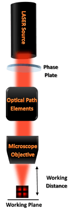
Design and Manufacture of Diffractive Optical Elements for high power lasers