INTRODUCTION

Diffractive beam samplers are used to monitor high power lasers where optical losses and wavefront distortions of the transmitted beam need to be kept to a minimum.
In most applications, most of the incident light must to continue forward, “unaffected,” in the “zero order” while a small amount of the beam is diffracted into a higher order, providing a “sample” of the beam.
By directing the sampled light in the higher order(s) onto a detector, it is possible to monitor, in real time, not only the power levels of a laser beam, but also its profile.

Principle of operation

The operational principle is quite straightforward. From a collimated input beam, the output beams exit from Diffractive Optical Element (DOE) with a separation angle that is determined during the design of the DOE based on the customer’s system requirements (See figure 1 below). The separation angle is highly accurate (<0.03mR error). The beams’ separation is designed for far-field so that as the beams continue to propagate after DOE, they become more well-defined.
Normally, the customer wishes to get well-focused spots at a certain distance. This is easily achieved by the addition of a simple focusing lens after the DOE, whose BFL (back focal length) determines the working distance (WD) to the multi-spot focal plane. See figure 2 below.
A Diffractive Beam Sampler allows the high power beam (zero order) to propagate along the optical axis, but produces two side beams with low energy. These two sample beams are located to the left and right of the main beam (-1 and +1 orders), and are characterized by a given separation angle between them and by a given sample power ratio requested by customer. The separation angle is twice the sampled angle (α in figure 1.)

Typical Set-Up

Figure 1: Beam Sampler DOE basic set-up

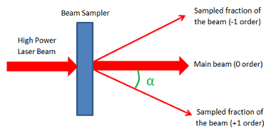
Figure 2: Beam Sampler DOE with focusing lens

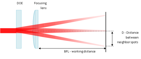
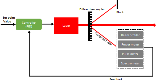
Figure 3: Application example: Laser stabilizer with PID controller

Choosing the right lens

Choosing the right lens for the application is quite easy using the following mathematical relationship between the Working distance WD, sampled angle and D (distance between sampled beam from optical axis and main beam [0 order]):

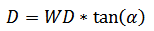
D: distance between sampled beam from optical axis and main beam [0 order]
WD: Working distance
α: Sampled angle (angle between sampled beam and main beam [see figure 1.])

The spot size at the focal plane is given by the formula:
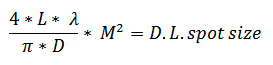
L: Working Distance
λ:  Wavelength
D:  Input Beam Size
M2:  M2 value of input laser beam

Design considerations and limitations

In sampling ratio 1% configuration, power efficiency will be ~97.5% in the main beam (0 order) and 1% in +1 and -1 orders. The remaining power is distributed among the other (parasitic) orders.

The minimum input beam size is determined by various design parameters specific to the application at hand, and is given as at least 3 times the size of the period in the DOE. The period in turn is given by the equation:
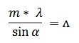
Λ = Period of DOE
m = diffraction order
λ = wavelength
α = sampled angle

In cases where the Period is very large, and the laser beam is very small, the user can widen the input beam using a beam expander that matches his/her wavelength and required magnification.

TOLERANCES

Normally, due to standard tolerances in etching, the sampling ratio can vary around the desired ratio in a specific range which differs according to the wavelength.